
A weld occurs when similar pieces of metal are joined by causing the interface to melt and blend prior to solidifying as a uniform metal joint. The process may be caused by heat, pressure or a combination of both. When heat alone is used the process is called fusion welding.
Pressure welding normally involves heating the surfaces to a malleable state and then forcing the metal together. The heating method can be electric current or friction resulting from moving one surface relative to the other.
The equipment used for welding metals is also associated with cutting metal. There are many allied welding processes.
Below are short introductions to some of the welding processes.
Soldering is suitable for light duty joining of sheets, tubes, electrical and electrical connections. It is an understated but widely used process through the sheet metal industry most commonly used to join brass and copper and light fabrications where welding would introduce too much heat. The solder is an alloy of lead-tin which melts at a temperature of 180 - 280o depending on the composition. The surfaces to be soldered are thoroughly cleaned and prepared with a flux. The material to be joined is preheated and the solder when applied wets the metal through the close joint and produces an intermetallic bond. The most favourable method is to ensure the gap to be filled is controlled to about 0,1mm then the solder is drawn into the joint by capillary action to produce a uniformly filled joint. The joint is heated using a soldering iron or a gas flame. It is important the surfaces are suitably positioned when the joint is being made and there are no separating forces.
The shear strength of a soldered joint is, depending on the solder composition and materials, within the range 30 to 45 N/mm2.
The flux is needed to remove any oxidation on the metal and to protect the surfaces from contamination and to reduce the surface tension of the filler to assist in penetration. For soft soldering the flux is generally zinc chloride or in a resin based form.
Brazing is a joining process which is similar to soldering but uses filler material that has a significantly higher melting point ( 450 to 800o ). Copper, Nickel, Silver are the most frequently-used base metals for brazing alloys. The process is used widely for joining and sealing on higher performance applications such as copper based alloys e.g. pipe fabrications, heat exchangers and vessels. It is also used to join brass when soldering and TIG welding is not suitable.
Brazed joints are stronger than soldered joints. The higher temperatures required for brazing can result in problems such as distortion of the fabrication. Various heating methods can be used including the most commonly gas torch, furnace, induction heating, resistance heating and molten flux bath of which are less common in the sheet metal and general fabrication sectors.
The shear strength of a brazed joint is dependent on the joint preparation but typically within the range 250-310 N/mm2.
Both brazing and soldering, the base metal parts being joined are not fused unlike all the other joining process considered on this page.
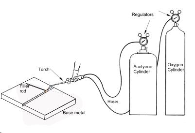
The gas welding process uses heat to produce fusion of the parent metal and filler rod, of which is achievable by burning a suitable gas in oxygen or air. Acetylene is the most popular gas used, since it burns in oxygen and gives a high flame temperature of 3100o - 3200o. C. Oxygen and acetylene stored pressurised in metal cylinders. The Gasses are passed through flexible tubes to the torch. The proportions of oxygen or acetylene can be adjusted so the flame can be neutral, or have either reducing or oxidising properties. For the majority of materials a neutral flame is used except for welding high carbon steel, aluminium and associated alloys then an oxidising flame is used.
The capital cost of gas welding equipment, oxyacetylene is low compared with that for arc welding. The equipment is also easily portable and the process is very versatile. However, it’s comparatively slow compared to arc welding if there is a considerable amount of welding to be done.
Oxyacetylene welding requires the following equipment.
1) A cylinder of oxygen (full pressure about 15MPa)
2) A cylinder of acetylene (full pressure about 1,7)
3) Pressure regulator valves for each cylinder
4) Hoses to transfer gas flow to torch.
5) Welding torch with various sizes of torch tips
The gas pressures at the torch are to be about 7 to 70 kPa each and can be regulated to achieve the desired flame.
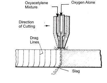
Flame cutting using an oxyacetylene flame is a well-known engineering and fabrication technique. The cutting torch may be manually operated if low accuracy is permissible, or if higher accuracies are required, the torch is mechanically mounted to a track system or an articulated arm and controlled numerically or by using a magnetic tracer system. An outer oxyacetylene gas flame is used to preheat the metal to around 1000oC. An inner by a jet of oxygen is then rapidly initiated which oxidises the red-hot metal, enabling thick materials to be cut. The cutting process is then progressed with both jets on
.
Electric Arc welding is an electric circuit comprising the electric current source, the feed and return path, the electrode and the work piece. The arc welding process involves the creation of a suitable small gap between the electrode and the work piece. When the circuit is made a large current flows and an arc is formed between the electrode and the work piece. The result of this process produces high temperatures causing the work piece and the electrode to melt. The electrode is consumable. It comprises of metal for the weld, a coating which burns off to form shielding gases which protect the weld from the air and a flux which combines with the nitrides and oxide generated at the point of the weld. When the weld solidifies a crust is formed from the impurities that were created in the weld process which are also known as Slag. The Slag is easily removed with a chipping hammer.
These two methods are the most commonly used welding processes in the sheet metal and general fabrication industry.
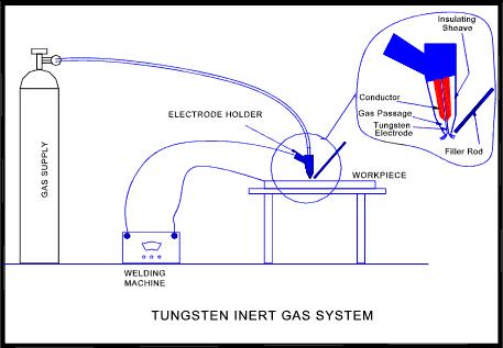
The Tungsten Inert gas (TIG) system uses an electrode of tungsten and an inert gas shield of argon or helium.
The TIG process was originally developed for welding magnesium and it is now widely used for the welding of aluminium, copper, mild steel, stainless steel, and a wide range of other metals that are difficult to weld such as brass. TIG welding can also be used to weld Alloy castings such as gear box covers and other various automotive engine and transmission parts. Consumable rods also referred to as filler wire may be used depending on the type of weld and the thickness of weld.
The Metal Inert Gas (MIG) Process uses a consumable electrode of wire form normally in a coil and an inert gas shield of carbon dioxide when welding carbon steel most commonly referred to as argon Co2 mix. The coiled electrode wire provides a continuous feed of filler metal allowing welds of any length without stopping. The inert gas shield eliminates slag spatter and allows for a cleaner and stronger weld. This process is used widely for general fabrications where weld aesthetics are less important. Generally MIG welding is a quicker process than TIG welding.
This process is not commonly used in the sheet metal industry. The process involves the welding arc being continuously submerged under a mound of granular flux. The raw metal is fed automatically and regulated which maintains the welding arc.
As the arc and the molten metal are covered with the mountain of flux, there is no spatter, sparks or smoke. The resulting weld is uniform with good physical and chemical properties.

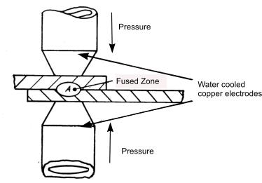
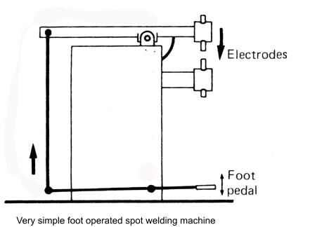
Spot welding utilises a high current at a low voltage which passes through a spot on two pieces of metal, usually sheet metal, for a short period of time melting the lapped materials together. This process is done using a spot welder. Resistance to the current flow results in localised heat generation which melts the metal between the copper electrodes. The electrodes or welding tongs exert a modest pressure forcing the two metal pieces together at the spot. The weld spot results at the interface.
The actual spot weld operation includes the following
SQUEEZE TIME - Time between pressure application and weld.
HEAT OR WELD TIME - Weld time.
HOLD TIME - Time that pressure is maintained after weld is made.
OFF TIME - Electrodes switched off to allow separation and movement of component to next position
The welding time can vary from 1 to 120 Hz. Assuming a 50 Hz supply in the UK e.g. 25 Hz = 0.5 seconds
The tip diameter can vary from 2.5mm to 15mm diameter the calculation based on the combined sheet thickness being welded.
A rough formula for mild steel sheet = Diameter of tip (mm) = 2.5mm + 2. Sheet thickness (mm)
Typical specification range
Arm length - 300mm to 450mm
Power rating - 1.5 KVA - 20 KVA
Rated Output - 3600A - 2,500A
Combined thickness of metal – 2mm to 6mm
Projection welding is similar to spot welding except that one of the surfaces in contact with the electrodes has a local projection. The projection defines the area of weld and not the size of the electrodes. The projection is normally on the thicker component or on the component having the highest resistance. The process generally results in the collapse of the projection when the weld is formed.
Seam welding is a similar principle to the spot welding process in which the current is fed continuously or intermittently to two copper alloy wheel electrodes which replace the rod electrodes used for spot welding. This process is ideal for producing fluid tight joints in cans. The sheet metal work pieces which are lapped over are passed through the copper rollers and seam welded together. The weld is continuous and uniform.
Solid state welding is a welding process which produces joining of metals at temperatures below the melting point of the base material without the need for a filler metal. Pressure is generally required but not essential. These welding processes include cold pressure welding, diffusion welding, explosion welding such as stud welding, forge welding, hot pressure welding, friction welding, roll welding and ultrasonic welding.
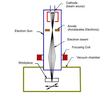
This is a specialised welding process. In this process consists of a concentrated beam of electrons which bombard the base metal, causing it to melt and fuse together. The process is most efficient when done in a vacuum. The size of the vacuum chamber limits the size of the work pieces that can be welded. Advantages of electron beam welding include the ability to produce welds of extremely high purity, ability to melt any known material, ability to weld dissimilar metals and the ability to welds depths as great as 150mm.
Electron beam welding is extremely costly for two main reasons;
1) the high cost of equipment
2) the time lost in pumping out the vacuum chamber between welds.
When the welds are not made in a vacuum, many advantages of the process are reduced.
(Light Amplification by Stimulated Emission of Radiation).
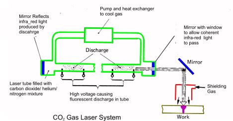
The laser beam is a highly concentrated beam of light with sufficient energy to generate localised heat at the metal surface to cause metal fusion. There are two types of lasers in use;
1) Gas lasers
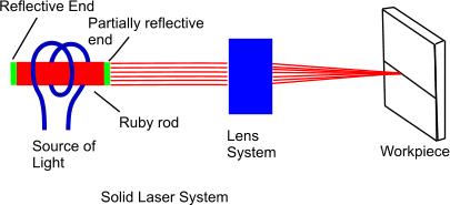
2) Solid lasers.
Gas lasers generate a continuous laser beam that is best suited to continuous welding and cutting. Solid lasers release their energy in pulses or short bursts at a rate of 6 to 10 per minute. Each pulse only lasts for a few millionths of a second resulting in the base metal is liquid for only moments and there is limited time for chemical reactions to occur. Therefore flux type protection is not required to obtain sound welds.
Laser systems can be precisely controlled using modern computer technologies and have sufficient power to weld and even vaporize any known metals. Other advantages include the ability to weld through transparent coverings and to position welds in locations impossible to reach with conventional welding equipment. However limited depth of penetration restricts the use of laser welding to relatively thin materials.
The welding process designations provided below are based on BS EN ISO 4063 and are used when identifying welds to BS EN 22553
1 Arc welding
11 Metal-arc welding without gas protection.
111 Metal-arc welding with covered electrode.
112 Gravity arc welding with covered electrode.
113 Bare wire metal-arc welding.
114 Flux cored wire metal-arc welding.
115 Coated wire metal-arc welding.
118 Firecracker welding.
13 Gas-shielded metal-arc welding
131 MIG welding: metal-arc inert gas welding
135 MAG welding: metal-arc active gas welding
136 Flux-cored wire metal-arc welding with active gas shield
14 Gas-shielded welding with non-consumable electrode
141 TIG welding: tungsten inert gas arc welding
149 Atomic-hydrogen welding
15 Plasma arc welding
18 Other arc welding processes
181 Carbon-arc welding
185 Rotating arc welding
2 Resistance Welding
21 Spot welding
22 Seam welding
221 Lap seam welding
225 Seam welding with strip.
23 Projection welding
24 Flash welding
25 Resistance butt welding
29 Other resistance welding processes
291 HF (High-Frequency) resistance welding
31 Oxy-fuel gas welding
311 Oxy-acetylene welding
312 Oxy-propane welding
313 Oxy-hydrogen welding
32 Air-fuel gas welding
321 Air-acetylene welding
322 Air-propane welding
4 Pressure welding
41 Ultrasonic welding
42 Friction welding
43 Forge welding
44 Welding by high mechanical energy
441 Explosive welding
45 Diffusion welding
47 Gas pressure welding
48 Cold pressure welding.
Other welding processes
71 Thermit welding
72 Electro-slag welding
73 Electro-gas welding
74 Induction welding
75 Light radiation welding
751 Laser beam welding
752 Arc image welding
753 Infrared welding
76 Electron beam welding
77 Percussion welding
78 Stud welding
781 Arc stud welding
782 Resistance stud welding


